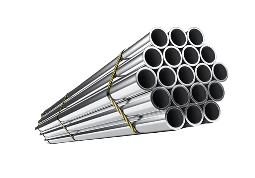
Stainless Steel 321 Flanges are specified for hot, welded pipelines. Plain 304 flanges have a weakness here: when they are welded or held hot for long periods, chromium combines with carbon at the grain boundaries, leaving the nearby metal low in chromium and open to corrosion. This issue is addressed by 321 due to the titanium element. Titanium combines with carbon first, so the weld heat-affected zone keeps its chromium and stays resistant to intergranular corrosion without post-weld solution annealing. For pipelines with temperatures exceeding about 540 °C (1000 °F) SS 321H is preferred.Its controlled 0.04% to 0.10% carbon gives higher creep and stress-rupture strength in long-term high temperature service. We supply both grades to ASTM A182 and ASME B16.5 / B16.47 standards from class 150 to 2500 and different types of flanges including weld neck, slip on, blind, socket weld, threaded and lap joint. Metinox Overseas supplies 321 and 321H flanges to refinery, petrochemical and power buyers in India, the GCC and other export markets, as part of its wider flanges range.

Table of Contents
- Specification Sheet for Stainless Steel 321 Pipe Flanges
- Stainless Steel 321 / 321H Flanges Chemical Properties
- SS 321 / 321H Flanges Mechanical Properties
- Physical Properties of SS 321 / 321H Flanges (WNR 1.4541 / 1.4878)
- Equivalent Grades: Stainless Steel DIN 1.4541 / 1.4878 Weld Neck Flanges and Other Designations
- Types of SS 321 / 321H Flanges
- SS 321H Flanges Dimensions: ASME B16.5 Class 150 Key Sizes
- SS 321 / 321H Flanges Weight Chart, Class 150 (lb)
- Applications of SS 321 and 321H Flanges in High Temperature Service
- Certification and PMI Checks Before Ordering SS 321 / 321H Flanges
- Request a Quote for SS 321 Threaded Flanges, Weld Neck Flanges and the Full 321H Range
- Completing the Line: Fittings and Pipe to Match Stainless Steel 321 Slip On Flanges
- Questions Buyers Ask About Stainless Steel 321 Flanges and 321H SS Flanges
Specification Sheet for Stainless Steel 321 Pipe Flanges
| Item | Detail |
|---|---|
| Material standard | ASTM A182 / ASME SA182, grades F321 (UNS S32100) and F321H (UNS S32109) |
| Product form | Forged or rolled flanges, solution annealed |
| Dimensional standards | ASME B16.5 (NPS 1/2 to NPS 24), ASME B16.47 Series A and B (NPS 26 to NPS 60), ASME B16.36 orifice flanges, ASME B16.48 line blanks, EN 1092-1, MSS SP-44 |
| Pressure classes (ASME) | 150#, 300#, 600#, 900#, 1500#, 2500# |
| Pressure ratings (EN) | PN 6 to PN 100 per EN 1092-1 |
| Facings | Raised face (RF), flat face (FF), ring type joint (RTJ), tongue and groove, male and female |
| Face finish | Stock finish to ASME B16.5, or as specified (serrated spiral, smooth) |
| Bore | Weld neck bore matched to the pipe schedule you specify (Sch 10S, 40S, 80S, 160, XXS) |
| Sizes | NPS 1/2 to NPS 60 (DN 15 to DN 1500) |
Stainless Steel 321 / 321H Flanges Chemical Properties
Per ASTM A182, weight %, maximum unless a range is shown.
| Element | F321 (S32100) | F321H (S32109) |
|---|---|---|
| Carbon (C) | 0.08 | 0.04 to 0.10 |
| Manganese (Mn) | 2.00 | 2.00 |
| Phosphorus (P) | 0.045 | 0.045 |
| Sulphur (S) | 0.030 | 0.030 |
| Silicon (Si) | 1.00 | 1.00 |
| Nickel (Ni) | 9.0 to 12.0 | 9.0 to 12.0 |
| Chromium (Cr) | 17.0 to 19.0 | 17.0 to 19.0 |
| Nitrogen (N) | 0.10 | 0.10 |
| Titanium (Ti) | 5 x (C + N) min, 0.70 max | 4 x (C + N) min, 0.70 max |
SS 321 / 321H Flanges Mechanical Properties
| Property | F321 | F321H |
|---|---|---|
| Tensile strength, min | 515 MPa (75 ksi) | 515 MPa (75 ksi) |
| Yield strength, 0.2% offset, min | 205 MPa (30 ksi) | 205 MPa (30 ksi) |
| Elongation in 50 mm (2 in) or 4D, min | 30% | 30% |
| Reduction of area, min | 50% | 50% |
| Heat treatment | Solution annealed, 1040°C (1900°F) min, liquid quench | Solution annealed, 1050°C (1925°F) min, liquid quench |
Physical Properties of SS 321 / 321H Flanges (WNR 1.4541 / 1.4878)
| Property | Value |
|---|---|
| Density | 8.0 g/cm³ (0.289 lb/in³) |
| Melting range | 1400°C to 1425°C (2550°F to 2600°F) |
| Modulus of elasticity | 193 GPa (28.0 x 10⁶ psi) |
| Mean thermal expansion, 0°C to 100°C | 16.6 µm/m·°C (9.2 µin/in·°F) |
| Thermal conductivity at 100°C | 16.1 W/m·K (9.3 Btu/h·ft·°F) |
| Specific heat, 0°C to 100°C | 500 J/kg·K (0.12 Btu/lb·°F) |
| Electrical resistivity | 720 nΩ·m |
Equivalent Grades: Stainless Steel DIN 1.4541 / 1.4878 Weld Neck Flanges and Other Designations
| Standard | 321 | 321H |
|---|---|---|
| UNS | S32100 | S32109 |
| EN number | 1.4541 | 1.4878 |
| EN name | X6CrNiTi18-10 | X8CrNiTi18-10 |
| JIS | SUS321 | SUS321H |
| BS (former) | 321S31 | 321S51 |
Types of SS 321 / 321H Flanges
The right type depends on how the flange joins the pipe, the pressure and temperature it must hold, and how often the joint will be opened.
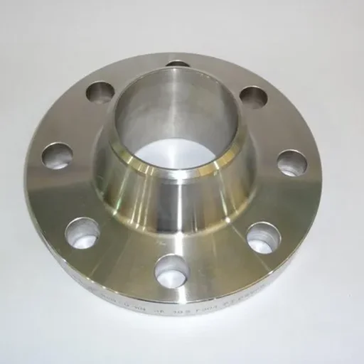
Weld Neck Flanges (WNRF):
These flanges are reinforced by the neck and are welded directly to the pipe, which guarantees a high mechanical strength and is most suitable in the high-load and high-heat process lines.
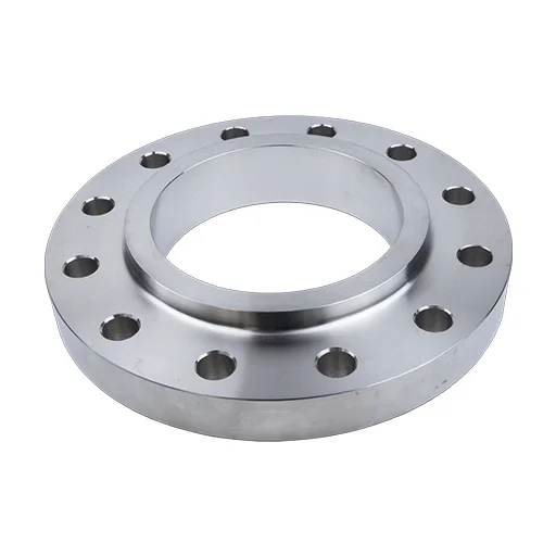
Slip-On Flanges (SORF):
The slides work well on the pipe and can be welded into place, so they are an easy option when fast installation and cost-effectiveness are required by the piping system that should be used.
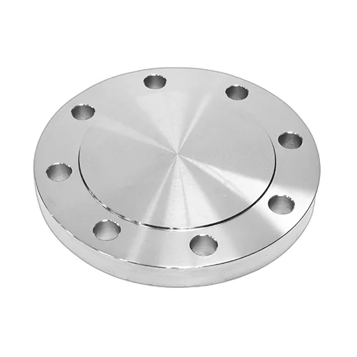
Blind Flanges (BLRF):
These flanges are used to seal pipe ends and openings of vessels, and they are best used in isolating a system, checking pressure, and closing it in the event of danger.
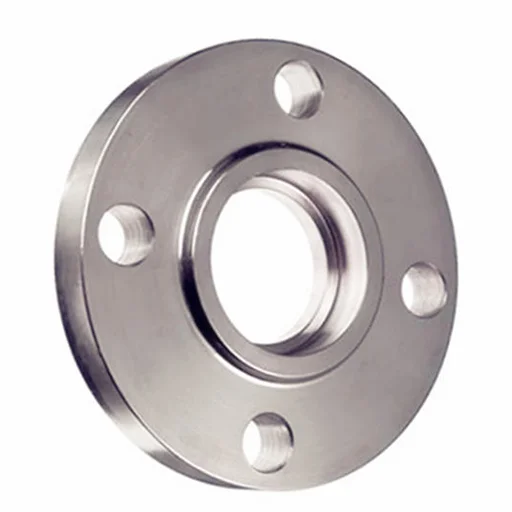
Socket Weld Flanges (SWRF):
They are designed to use compact piping layouts with high-pressure piping systems that are small-diameter joints that are powerful and leak-free.
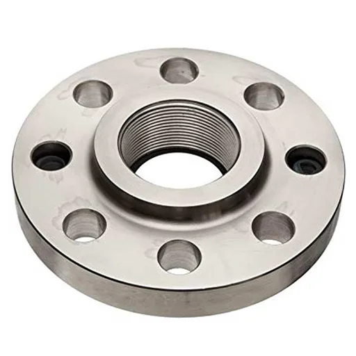
Threaded Flanges:
They are installed without welding with internal threads and are used in low-risk, removable and serviceable piping designs.
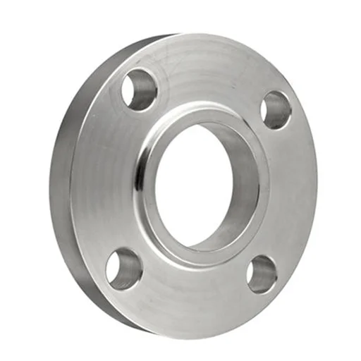
Lap Joint Flanges:
These flanges, coupled with stub ends to provide flexibility, are ideal in cases where the system needs to be dismantled frequently with an adjustment in alignment and cleaning.
SS 321 Weld Neck Flange (WNRF)
A tapered hub is butt welded to the pipe, spreading stress smoothly into the line. It is the standard choice for fired heater outlets and hot reactor lines, where pressure, high temperature and thermal cycling act on the joint together.
SS 321H Long Weld Neck Flange
The hub extends as a long barrel that serves as a nozzle neck on vessels, exchangers and columns. 321H is specified where the nozzle runs above about 540 °C and creep strength governs the design.
SS 321 Slip On Flanges (SORF)
This flange slides over the pipe and is fillet welded inside and out. It is quick to fit up and costs less than a weld neck, which suits lower pressure hot air, exhaust and utility lines.
SS 321 Spectacle Blind Flanges
A paddle and spacer joined by a web, made to ASME B16.48. It positively isolates hot process lines during maintenance and shows at a glance whether the line is open or closed.
SS 321 Socket Weld Flanges
The pipe sits in a counterbored socket and is fillet welded on the outside. It gives a strong joint on small bore lines, typically NPS 2 and below, such as instrument, drain and vent connections on hot equipment.
SS 321H Ring Type Joint Flanges
A machined groove takes a metal ring gasket for Class 900 and above, or for lines with heavy temperature cycling where a spiral wound gasket on a raised face could relax. This makes it common on high pressure steam and hydroprocessing service.
Not sure which flange fits your application? Share your size, pressure class and quantity, and our team will recommend the right type with a quick quote. Get a Free Quote
SS 321H Flanges Dimensions: ASME B16.5 Class 150 Key Sizes
Dimensions below are for Class 150 weld neck and slip on flanges, metric first with inches alongside. Higher classes have larger outside diameters, thicker sections and more or larger bolts. Ask for the drawing for your class and type.
| NPS | DN | Pipe OD, mm (in) | Flange OD, mm (in) | Bolt circle, mm (in) | Bolts, number x size | Bolt hole, mm (in) |
|---|---|---|---|---|---|---|
| 1/2 | 15 | 21.3 (0.840) | 90 (3.50) | 60.3 (2.38) | 4 x 1/2 in | 16 (0.62) |
| 3/4 | 20 | 26.7 (1.050) | 100 (3.88) | 69.9 (2.75) | 4 x 1/2 in | 16 (0.62) |
| 1 | 25 | 33.4 (1.315) | 110 (4.25) | 79.4 (3.12) | 4 x 1/2 in | 16 (0.62) |
| 1 1/2 | 40 | 48.3 (1.900) | 125 (5.00) | 98.4 (3.88) | 4 x 1/2 in | 16 (0.62) |
| 2 | 50 | 60.3 (2.375) | 150 (6.00) | 120.7 (4.75) | 4 x 5/8 in | 19 (0.75) |
| 3 | 80 | 88.9 (3.500) | 190 (7.50) | 152.4 (6.00) | 4 x 5/8 in | 19 (0.75) |
| 4 | 100 | 114.3 (4.500) | 230 (9.00) | 190.5 (7.50) | 8 x 5/8 in | 19 (0.75) |
| 6 | 150 | 168.3 (6.625) | 280 (11.00) | 241.3 (9.50) | 8 x 3/4 in | 22 (0.88) |
| 8 | 200 | 219.1 (8.625) | 345 (13.50) | 298.5 (11.75) | 8 x 3/4 in | 22 (0.88) |
| 10 | 250 | 273.0 (10.750) | 405 (16.00) | 362.0 (14.25) | 12 x 7/8 in | 26 (1.00) |
| 12 | 300 | 323.8 (12.750) | 485 (19.00) | 431.8 (17.00) | 12 x 7/8 in | 26 (1.00) |
| 16 | 400 | 406.4 (16.000) | 595 (23.50) | 539.8 (21.25) | 16 x 1 in | 29 (1.12) |
| 24 | 600 | 610.0 (24.000) | 815 (32.00) | 749.3 (29.50) | 20 x 1 1/4 in | 35 (1.38) |
Tolerances follow ASME B16.5. Weld neck bore and hub end are machined to the wall of the mating pipe, so state the pipe schedule on the order.
SS 321 / 321H Flanges Weight Chart, Class 150 (lb)
| NPS | Slip On (SORF) | Threaded (NPT) | Socket Weld (SWRF) | Lap Joint | Blind (BLRF) | Weld Neck (WNRF) |
|---|---|---|---|---|---|---|
| 1/2″ | 1 | 1 | 2 | 1 | 2 | 2 |
| 3/4″ | 2 | 2 | 2 | 2 | 2 | 2 |
| 1″ | 2 | 2 | 2 | 2 | 2 | 3 |
| 1 1/4″ | 3 | 3 | 3 | 3 | 3 | 3 |
| 1 1/2″ | 3 | 3 | 3 | 3 | 4 | 4 |
| 2″ | 5 | 5 | 5 | 5 | 5 | 6 |
| 2 1/2″ | 8 | 8 | 8 | 8 | 7 | 10 |
| 3″ | 9 | 9 | 9 | 9 | 9 | 11.5 |
| 3 1/2″ | 11 | 12 | 11 | 11 | 13 | 12 |
| 4″ | 13 | 13 | 13 | 13 | 17 | 16.5 |
| 5″ | 15 | 15 | 15 | 15 | 20 | 21 |
| 6″ | 19 | 19 | 19 | 19 | 27 | 26 |
| 8″ | 30 | 30 | 30 | 30 | 47 | 42 |
| 10″ | 43 | 43 | 43 | 43 | 70 | 54 |
| 12″ | 64 | 64 | 64 | 64 | 123 | 88 |
| 14″ | 90 | 90 | 90 | 105 | 140 | 114 |
| 16″ | 106 | 98 | 98 | 140 | 180 | 140 |
| 18″ | 130 | 130 | 130 | 160 | 220 | 165 |
| 20″ | 165 | 165 | 165 | 195 | 285 | 197 |
| 22″ | 185 | 185 | 185 | 245 | 355 | 225 |
| 24″ | 220 | 220 | 220 | 275 | 430 | 268 |
Applications of SS 321 and 321H Flanges in High Temperature Service
321 is the usual choice for welded hot lines that cycle through shutdowns, while 321H is kept for continuous service above about 540 °C, where creep life governs the design.
| Sector | Where SS 321 / 321H Flanges Are Used |
|---|---|
| Refining and petrochemicals | Fired heater outlets, reactor effluent lines, hydroprocessing units, catalytic reformer piping |
| Gas processing and LNG | Hot regeneration gas lines, thermal oxidiser and incinerator connections |
| Power and water | Superheater and reheater connections, steam lines, HRSG piping |
| Fertilizer | Hot process gas lines in ammonia and urea plants |
| Chemical processing | Heat exchanger nozzles and hot process lines with mildly corrosive media |
| Offshore and upstream oil and gas | Exhaust, flare and hot utility lines, within the chloride and sour service limits given below |
Certification and PMI Checks Before Ordering SS 321 / 321H Flanges
Every forging should be traceable to a heat number on the flange and the mill test certificate. Metinox Overseas supplies mill test certificates to EN 10204 3.1 as standard, with 3.2 certification witnessed by a third party inspector on request.
Things to check on any 321 or 321H order, whoever supplies it:
- The certificate names the A182 grade ordered. A 321 certificate is not acceptable for a 321H line.
- Carbon on 321H certificates sits inside 0.04% to 0.10%.
- Titanium meets the ratio required by the specification edition.
- Positive material identification (PMI) on each piece. 321, 304 and 347 look identical, and a mixed up flange in a hot line is a serious risk. PMI by XRF shows titanium, which separates 321 from 304 and 347.
- Marking on each flange: manufacturer's mark, grade, class, size, heat number and standard.
Request a Quote for SS 321 Threaded Flanges, Weld Neck Flanges and the Full 321H Range
Send your line list or enquiry with grade, size, class and quantities, and our team will reply with pricing and delivery. Include your material specification if your project issues one, so the quotation covers every requirement from the start.
Request a QuotationCompleting the Line: Fittings and Pipe to Match Stainless Steel 321 Slip On Flanges
A hot service line needs the same grade from pipe to fitting to flange, with matching certificates.
- 321 and 321H pipe to ASTM A312 TP321 / TP321H: [LINK NOT CONFIRMED: page URL needed]
- 321 and 321H buttweld fittings to ASTM A403 WP321 / WP321H: [LINK NOT CONFIRMED: page URL needed]
- 347 and 347H flanges, the niobium stabilised alternative some refinery specifications prefer
- All stainless steel flanges
Looking for High-Quality SS 321 Flanges?
Let us support your projects with quality, precision, and performance.
Questions Buyers Ask About Stainless Steel 321 Flanges and 321H SS Flanges
Both are titanium stabilised ASTM A182 grades. F321 allows up to 0.08% carbon. F321H requires 0.04% to 0.10% carbon, which gives higher creep strength for long term service above about 540°C. Specify the grade on the line list, as certificates must match it.
Only within the environmental limits set in ISO 15156-3 and at a maximum hardness of 22 HRC. Grade 321 is mainly selected for high temperature service. For wet sour duty outside those limits, a duplex or nickel alloy is usually needed, so confirm with your materials engineer.
Both grades require 515 MPa minimum tensile strength, 205 MPa minimum yield strength, 30% minimum elongation and 50% minimum reduction of area. ASTM A182 sets no maximum hardness for these grades. A hardness limit applies only if your specification or NACE MR0175 calls for one.
321 corresponds to EN 1.4541 (X6CrNiTi18-10). 321H is often cross referenced to 1.4878, but the chemistry limits are not identical, so check your specification before accepting it as a substitute.
Send the grade, standard, flange type, facing, size, class, bore or pipe schedule, quantity, certification level, any third party inspection or extra testing, the destination port and the required delivery date.
Enquire Now
Get pricing within 24 hours!